CNC Machine Vibration Analysis: Diagnosing Problems Before They Escalate
Share Post
In the realm of precision machining, tolerance is everything. When you are holding dimensions within ten-thousandths of an inch, the physical stability of your CNC machinery is paramount. Yet, every day, machine shops throughout Southern California battle a silent, destructive force that degrades surface finishes, snaps cutting tools, ruins expensive workpieces, and quietly destroys spindle bearings: abnormal vibration.
Vibration is an inherent part of metal cutting. The interaction between a rotating tool and a metal workpiece naturally generates physical frequencies. However, when these frequencies cross the line from normal operational feedback to abnormal, unchecked oscillation, they become a major risk. Left undiagnosed, minor vibrations escalate into catastrophic mechanical failures, resulting in thousands of dollars in repair costs and weeks of lost production.
In this deep-dive technical article, we explore the primary sources of abnormal CNC vibration, the advanced measurement tools used to diagnose them, the basics of frequency analysis, and how to know when to call in the professionals at In-House CNC Service LLC.
The Physics of CNC Vibration: Why It Is Your Machine’s Worst Enemy
To effectively combat vibration, we must first understand the physics behind it. In a CNC machine, vibration is essentially the rapid, oscillatory motion of mechanical components about their position of equilibrium. When a cutting tool engages with a workpiece, it does not do so in a perfectly smooth, continuous shear. Instead, each individual flute of the endmill or tooth of the face mill strikes the metal with immense force, creating a series of rapid impulses.
Under normal conditions, the massive cast-iron frame, heavy linear guide rails, and pre-loaded bearings of a high-quality CNC machine are designed to absorb and dampen these cutting impulses. However, when a component loses its structural stiffness, becomes unbalanced, or begins to wear, its natural damping capacity is compromised. This allows the cutting forces to feed back into the machine’s structure, creating a self-excited vibration loop known as regenerative chatter. Chatter is highly destructive because it grows exponentially, generating forces that can easily fracture carbide tools, chip spindle noses, and cause permanent alignment deviations in your machine’s axes.
The Major Sources of Abnormal CNC Vibration
Abnormal vibration is rarely a simple issue; it is typically the physical symptom of an underlying mechanical, structural, or electrical problem. The most common culprits include:
- **Spindle Imbalance:** The spindle is the heart of your CNC machine, often rotating at speeds exceeding 10,000 to 20,000 RPM. Even a microscopic weight imbalance in the spindle shaft, drawbar assembly, or tool holder can generate immense centrifugal forces, causing severe high-frequency vibration.
- **Bearing Wear and Degradation:** As spindle or axis bearings age, their ultra-precise rolling elements and raceways develop micro-pitting, spalling, or loss of lubrication. This wear creates a highly destructive, high-frequency vibration signature that accelerates rapidly under heavy cutting loads.
- **Ball Screw and Linear Guide Wear:** If an axis ball screw is worn, has excessive backlash, or if the linear guide trucks have lost their pre-load, the entire axis will shudder and vibrate during interpolation or rapid movements.
- **Loose Workholding or Fixtures:** Vibration isn’t always inside the machine’s drive train. A workpiece that is not rigidly clamped, or a fixture with loose mounting bolts, will vibrate violently under the impact of the cutting tool’s teeth.
- **Harmonic Resonance:** Every physical object has a natural resonant frequency. If the spindle speed or cutting tool pass-frequency aligns perfectly with the natural frequency of the machine’s frame, casting, or fixture, the vibration will amplify exponentially, creating a loud, deafening chatter.
The Hidden Costs of Ignoring Vibration
Many machine shop managers adopt a “run-to-fail” approach, believing that as long as the machine is producing parts that pass inspection, any vibration is merely a cosmetic nuisance. This is an incredibly short-sighted and expensive strategy. The hidden costs of ignoring minor vibration include:
- **Drastically Reduced Tool Life:** Vibrating spindles cause cutting tools to chip and wear up to 500% faster. You will find yourself spending thousands of dollars extra per month on replacement solid carbide endmills, indexable inserts, and tool holders.
- **Sub-par Surface Finishes:** Vibration leaves micro-grooves, chatter marks, and witness lines on the finished workpiece. If you are machining high-precision parts for medical, aerospace, or automotive clients, these cosmetic and dimensional defects will result in high scrap rates and rejected shipments.
- **Accelerated Wear on Secondary Components:** Vibration doesn’t stay confined to the spindle. It travels through the entire machine, loosening electrical connections in the cabinet, fatiguing hydraulic lines, wearing out ballscrew support bearings, and causing linear guide blocks to lose their precision pre-load.
Advanced Diagnostic Tools: Measuring the Unseen
To diagnose abnormal vibration before it causes a catastrophic blowout, technicians and maintenance managers rely on specialized measurement hardware. Trying to locate a vibration source by “feel” or “ear” is highly inaccurate and often leads to replacing perfectly good parts. Professional diagnostic suites utilize:
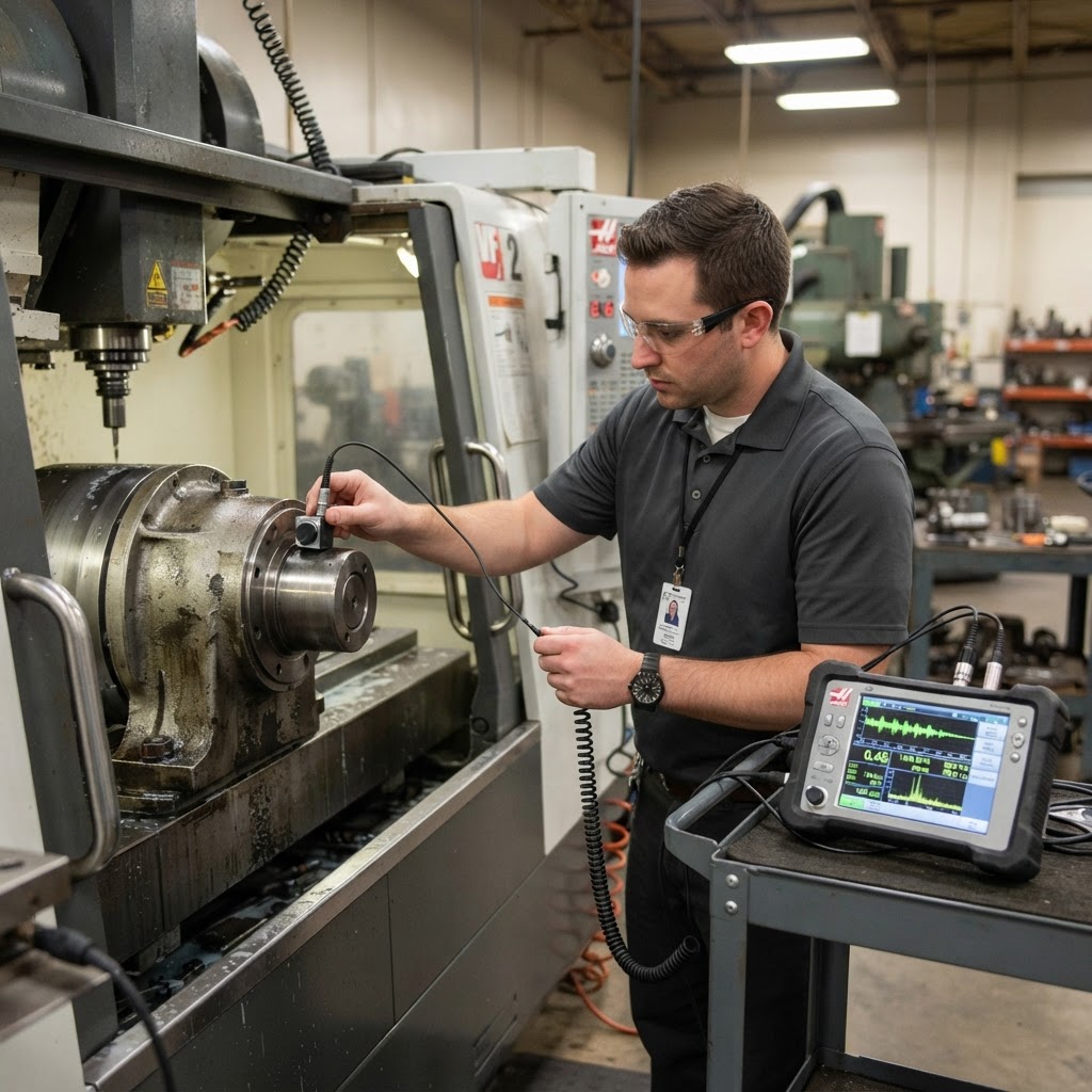
- **Piezoelectric Accelerometers:** These highly sensitive sensors are physically attached (via magnets, wax, or threaded studs) to the machine’s spindle housing, casting, or motor mounts. They convert physical mechanical movement into electrical signals.
- **Handheld Vibration Meters:** Excellent for quick, routine spot-checks, these portable devices measure overall vibration levels in terms of displacement (mils), velocity (inches per second – IPS), or acceleration (g’s).
- **Multi-Channel Spectrum Analyzers:** These advanced systems capture vibration signals over time and process them using mathematical algorithms to display them in the frequency domain.
How to Read an FFT Spectrum: A Guide for Shop Foremen
To give you a better understanding of how we analyze your machinery, let’s break down how to read a typical Fast Fourier Transform (FFT) spectrum. When we mount our sensors to your spindle housing and run the machine through its speed range, our software generates a live frequency plot.
The vertical axis shows the amplitude of the vibration, which represents how far the component is physically moving. We typically measure this in velocity (Inches per Second, or IPS) because velocity is the best overall indicator of structural fatigue and mechanical severity. The horizontal axis shows the frequency of the vibration, measured in Hertz (cycles per second) or CPM (Cycles Per Minute).
When we analyze the graph, we look for distinct, sharp “peaks” rising above the noise floor. Each peak acts as a mechanical fingerprint. For example, if a machine is running at 6,000 RPM, the fundamental rotational frequency (referred to as “1X”) is exactly 100 Hz. If we see a massive peak at exactly 100 Hz, we know with mathematical certainty that the issue is directly related to spindle imbalance or a bent shaft. If the peak is at 200 Hz (2X) or 300 Hz (3X), it typically indicates misalignment in the coupling between the motor and the spindle.
Basics of Frequency Analysis: Time Domain vs. Frequency Domain
To truly understand what is happening inside a vibrating CNC machine, we must look at **Frequency Analysis**.
- **The Time Domain:** A standard vibration sensor records movement over time. The resulting graph looks like a chaotic, squiggly wave. While this tells us *how much* the machine is vibrating, it tells us very little about *why*.
- **The Frequency Domain (FFT Analysis):** By applying a mathematical formula called the **Fast Fourier Transform (FFT)**, we can separate that chaotic, complex wave into its individual frequency components. Think of it like a prism splitting white light into its individual colors.
On an FFT spectrum graph, the horizontal axis represents frequency (measured in Hertz [Hz] or Cycles Per Minute [CPM]), and the vertical axis represents the amplitude (severity) of the vibration. Because different mechanical faults vibrate at very specific, predictable frequencies, a technician can look at the “peaks” on an FFT graph to pinpoint the exact component at fault.
Deciphering Vibration Signatures: What the Peaks Mean
An expert CNC technician uses the FFT spectrum as a diagnostic map. Here is what specific vibration signatures typically indicate:
- **1X Spindle Run-Speed Peak (e.g., 200 Hz peak at 12,000 RPM):** A massive spike at the exact rotational frequency of the spindle indicates a physical weight imbalance, a bent shaft, or severe spindle runout.
- **High-Frequency Broad Peak (e.g., 2,000 Hz to 5,000 Hz):** A broad band of high-frequency energy, often accompanied by smaller “sideband” peaks, is the classic signature of failing spindle bearings or bearing raceway damage.
- **Sub-Harmonic Peaks (e.g., 0.5X run-speed):** Vibration occurring at exactly half the spindle speed often indicates mechanical looseness, such as a loose spindle housing, worn mount bolts, or structural play.
- **Varying Axis-Speed Peaks:** If the vibration frequency shifts in direct proportion to the linear speed of an axis (X, Y, or Z), the issue lies in the axis drive motor, ball screw bearings, or linear guide trucks rather than the spindle.
Implementing Proactive Vibration Audits
Waiting for a CNC machine to produce terrible surface finishes or start screaming before addressing vibration is a highly expensive strategy. Forward-thinking machine shops integrate regular vibration audits into their preventative maintenance programs:
- **Establish a Baseline:** When a machine is new, newly rebuilt, or operating perfectly, record its baseline vibration signature.
- **Perform Monthly Spot-Checks:** Measure and log the overall velocity (IPS) on the spindle nose and axis housings monthly.
- **Trend the Data:** If a spindle’s vibration level climbs from 0.05 IPS to 0.15 IPS over three months, you have an early warning. You can schedule a bearing replacement or spindle balance during a planned weekend shutdown, avoiding an unplanned emergency breakdown mid-production.
When to Call In-House CNC Service LLC
While shop operators can monitor basic vibration, performing advanced FFT analysis, precision spindle balancing, and mechanical restoration requires specialized expertise and high-end equipment.
If you notice:
- Severe, unexplained chatter that persists across different tooling and speeds
- A high-pitched, grinding, or whining noise coming from your spindle housing
- Rapid tool wear or a sudden degradation in part surface finish (witness marks, cross-hatching)
- High vibration levels during overall spot-checks
It is time to call In-House CNC Service LLC at (951) 540-4820. Our team, led by Jason Wutzke, provides on-site vibration diagnostics, spindle dynamic balancing, bearing replacements, and comprehensive machine geometry alignment throughout Southern California. We utilize state-of-the-art diagnostic gear to isolate your mechanical issues with absolute precision, saving you from unnecessary downtime and expensive trial-and-error parts replacement.
Conclusion: Safeguard Your Precision
Don’t let abnormal vibration eat away at your shop’s profits, tooling, and machine lifespan. By understanding the science of vibration analysis and partnering with a trusted local expert, you can keep your CNC machinery operating at peak efficiency. Contact **In-House CNC Service LLC** today to keep your operations smooth, stable, and highly productive.